A Curious IBM PS/2 Model 80 Clone By Sentec Data
Sometimes, when you go to get rid of something small, you end up finding something bigger that you just have to drag back home. Last friday, my friend h4xxel was throwing out a broken lightbulb when he saw something huge gray and boxy sitting in the electronics dumpster. It looked interesting enough for him to drag the massive thing back up to his apartment.
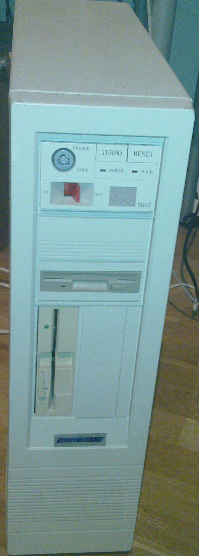
Figure 1 - A beast of a machine. Apparently it looks like a PS/2 Model 80.
1 The Find
Upon closer inspection, this turned out to be an intel 386 DX based system branded "Sentec Data". On visual inspection, it appeared to contain a 5¼ inch HD floppy drive, a 3½ HD floppy drive, some kind of MFM harddrive with controller, a VGA controller and a multi-purpose I/O card. It's not a multimedia machine, but everything needed seemed to be there. See figure 2 for an overview of the insides in the state the machine was found. There's a surprising lack of dust considering the age of the machine.
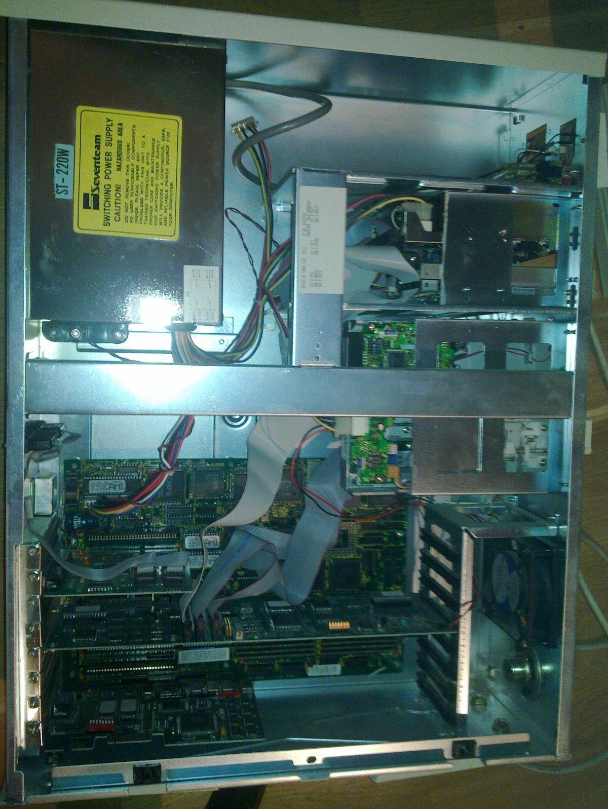
Figure 2 - Inside the computer in the state it was found
As with many of these old machines, the on-board RTC battery had started leaking. Somewhat unusually for a machine like this, there is also an LR06 battery holder for four batteries, with a lead that connects to the motherboard. This holder was populated with leaky batteries. Despite all the battery corrosion, the motherboard seemed to have escaped unharmed. The batteries were promptly removed.
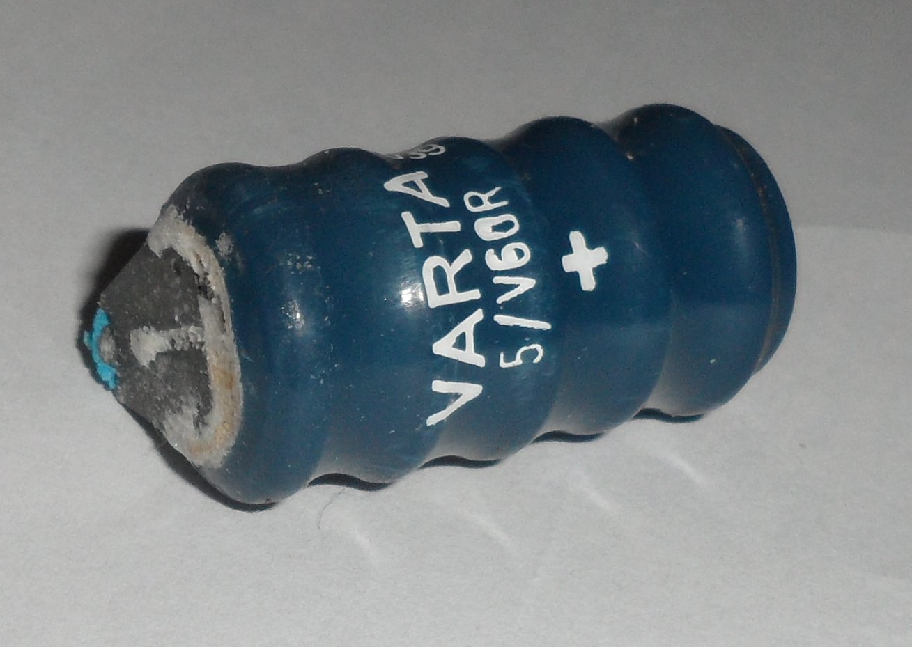
Figure 3 - The removed RTC battery
Things looked bright for this computer. The moment of truth: Will it power on? The clunking power switch was flipped and... Nothing.
2 The Troubleshooting
When the machine was powered on, at least the power supply seemed to work. The disk was whirring up, fans were making fan noises, but that was it. No POST screen, no beeps, no anything.
With my background of watching a lot of videos with uxwbill talking about old computers, I pretty quickly suggested to h4xxel that he "simplify the configuration". This means unplugging everything that isn't strictly necessary to see if it lives or not. With all the ISA cards removed and only the speaker for aliveness indication, there still was no sign of life when powered up.
At this point, suspicions were aimed at the power supply. Did it blow when the previous owner tried turning it on after many years in a closet? Voltages were checked and... They all seemed alright. Bummer. Could it be something annoying like defective RAM? The RAM modules where of an early 30 pin SIMM type with pin header connection rather than a card edge socket, as can be seen in figure 4.
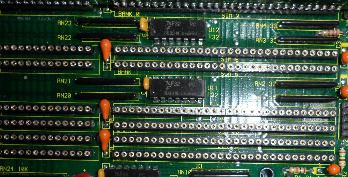
Figure 4 - The header type socket used for RAM on this motherboard
H4xxel however went right onto the motherboard with the oscilloscope to get to the bottom with it. The i387 coprocessor slot offerd plenty of test points, as can be seen in figure 5.
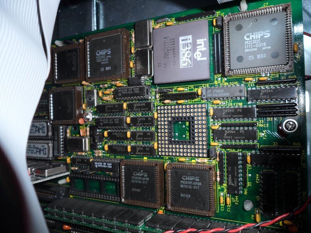
Figure 5 - The CPU, co-processor sockets and most of the chipset.
This quickly gave a hint of what was going wrong. The RESET line was stuck high. Looking at the datasheet for the i386 CPU, RESET is active high, so the computer was constantly in reset-state with the power on. That'd explain the lack of life signs!
Say what you want about Chips&Technologies chipsets, but you got to love that all datasheets are available online. The 82C301/82C302/82A303 .. chips on the motherboard is a dead giveaway, the motherboard is using the AT/386 CHIPSet™, which has an overview datasheet available. Skimming through verified my suspicion that the CPU RESET-signal is generated by the chipset. The RESET generation logic in the chipset takes two inputs, one from the keyboard controller (once upon a time, IBM for some reason thought the keyboard controller was a good place to connect the system RESET line) and one from the POWER_GOOD signal from the power supply. Measuring the POWER_GOOD line on the power supply gave the proper voltage (+5v when power levels are good) yet on the chipset, the input was low! This was re-assuring, the problem is probably not a fried chipset.
H4xxel continues to trace the POWER_GOOD reset line and eventually finds the reset circuit. This also merges the input from the front panel reset button. It turned out to be a very complicated circuit. No issue could be found among the components, they seemed to act properly. Apart from the output not being the expected one considering the inputs to the circuit. This reset circuit is conveniently located right by the RTC battery, so it's possible that subtle damage had occurred. H4xxel bodged a resistor onto the POWER_GOOD input to the reset circuit, and the computer started its POST!
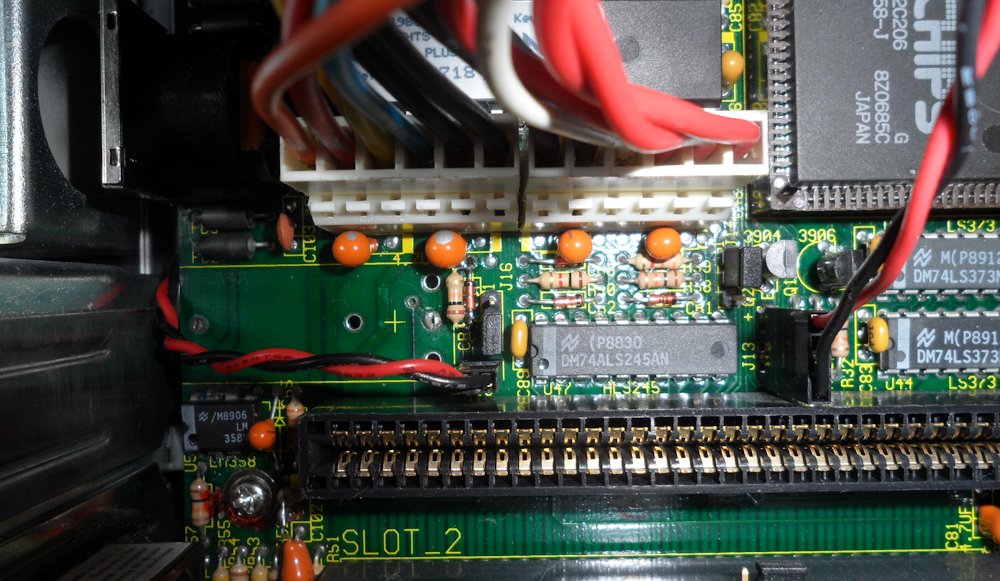
Figure 6 - The area around the RTC battery, including most of the reset circuit
3 The Clone Awakens From its Slumber
As the POST starts, a sickly sounding sequence of ticks is emitted from the system beeper, the memory test is running. And I say sickly, because it's slower than normal on 386 systems, and the ticks come at an irregular interval, but it's a memory test nontheless!
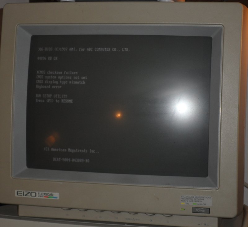
Figure 7 - Finally, a POST! Disregard the keyboard error, no keyboard was plugged in
The POST screen also lets us know the BIOS was made for "ABC Computer Co, Ltd." This appears to be a japanese motherboard manufacturer, which is supported by the amount of japanese parts and writing on the PCB. Our guess is that this motherboards complete model number is: "ABC Computer Co, Ltd. PRECISE 386", which seems almost identical to the "ABC Computer Co, Ltd PRESTIGE 386" that I can find information about online. The main difference between them is that the PRECISE model has three 8-bit ISA slots rather than two, which means the PRECISE also has one less 16-bit ISA slot.
Since the CMOS was cleared, important stuff like harddrive parameters were not present. There was also a strange error message, "XCMOS checksum failure", despite saving new CMOS settings. I'll get back to that later. The drive parameters were not printed on the harddrive, but a google search on the model number presented them. It's a 44 MB MFM harddrive. Despite its parameters being entered into BIOS, booting from it failed, and BIOS would show a "Drive C: error" message during POST.
Earlier, h4xxel had noticed the display on the front was stuck saying "08 MHz", the turbo button did not seem to do anything. Turns out it didn't even have a cable, and the motherboard did not have anywhere to plug it in. Before digging out a boot floppy, we noticed the BIOS has a built in diagnostic utility. It provided some basic tests, and among other things, we could tell that the VGA adapter was working fine. The tests seemed to be running quite slowly though, maybe the system was really running at an effective speed of 8 MHz?
Oh well, time to bring out a boot floppy. The hardware seemed to be functioning well, apart from the harddrive. Then, when running Microsoft Diagnostics, it suddenly found an installation of windows. Did the harddrive just start working?
Not quite. A phenomena noticed in the diagnonsis utility of the BIOS carried over to DOS, the C/H/S parameters were incorrect, DOS would always report 26 sectors no matter what was configured. This meant that some directories could be listed, and some files could even be read, assuming the data was on sector 17 or lower. While looking around on the drive, we found a directory with system utilities. I instantly recognised them, when looking around for the missing turbo button header, I found a website describing a motherboard very simlar to ours. It mentiones a setup tool to write settings into the chipset for RAM module size. I had previously been unsuccessful finding this utility, but here it was!
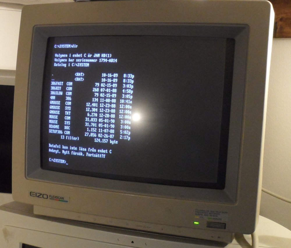
Figure 8 - The directory contining the missing system utilities, with a read error during free space calculation
Sadly, the files could not be copied from the harddrive due to read errors. However, the file names were enough to track down a copy of the files online. Among the setup tool there was also the utilities 386SLOW, 386FAST and 386KEY. These allow the CPU speed to change, and this is probably what we need to get the system up to 25 MHz! After copying over the utilities found online to a floppy, we found that running 386FAST would change the front display to show 25 MHz. I think we found the turbo button! Running the SETUP386 utility with the preset for this systems memory configuration (four 1M modules,) the "XCMOS checksum failed" error was no more. In case you have a 386 Chips & Technologies based systed with this error, you may find these utilities useful. The 386SLOW/FAST/KEY utilities are also included: http://f.rdw.se/386drv.zip
After loading the RAM parameters (and a scary amount of other chipset parameters) using SETUP386, the POST memory test was running much better. The clicks came at a regular interval and skipping the test gave a solid "brrrrrrrrr" noise. This system was starting to shape up.
4 The Restoration
To get this system into a usable state, we decided to get rid of the MFM disk and controller. The disk itself is probably fine. However, the BIOS seems to have some very buggy MFM drivers, and we could not figure out how to work around the problem with wrong C/H/S parameters being reported. As the BIOS expected MFM drives, it did not have built in IDE support. As my spare IDE controller does not have an option ROM, booting from the IDE device was not possible. My spare SCSI controller on the other hand does have an option ROM, so we replaced the MFM controller with a SCSI controller. The IDE controller was also installed to connect a CD-ROM drive, as none of our spare sound cards had an IDE connector.
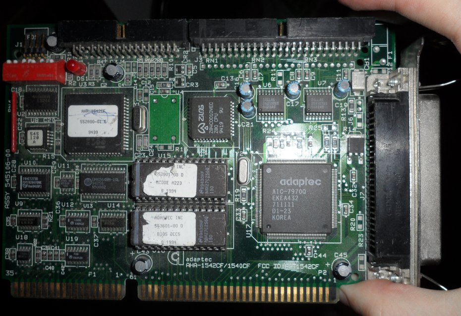
Figure 9 - The SCSI controller used. Its floppy controller was disabled as the IDE controller had a floppy controller too
A soundcard and a NIC was also installed, with the enourmous amount of room space this computes takes, it needs to be useful for something! With the SCSI controller installed, installing DOS was a breeze, and the installation of Windows 3.11 for workgroups seemed uneventful. The NIC started acting up, but at this point, the system was approaching usable, and the main adventure was over. At this link, you can find some misc. photos of the system that I did not use in this post: http://i.rdw.se/sentec/misc
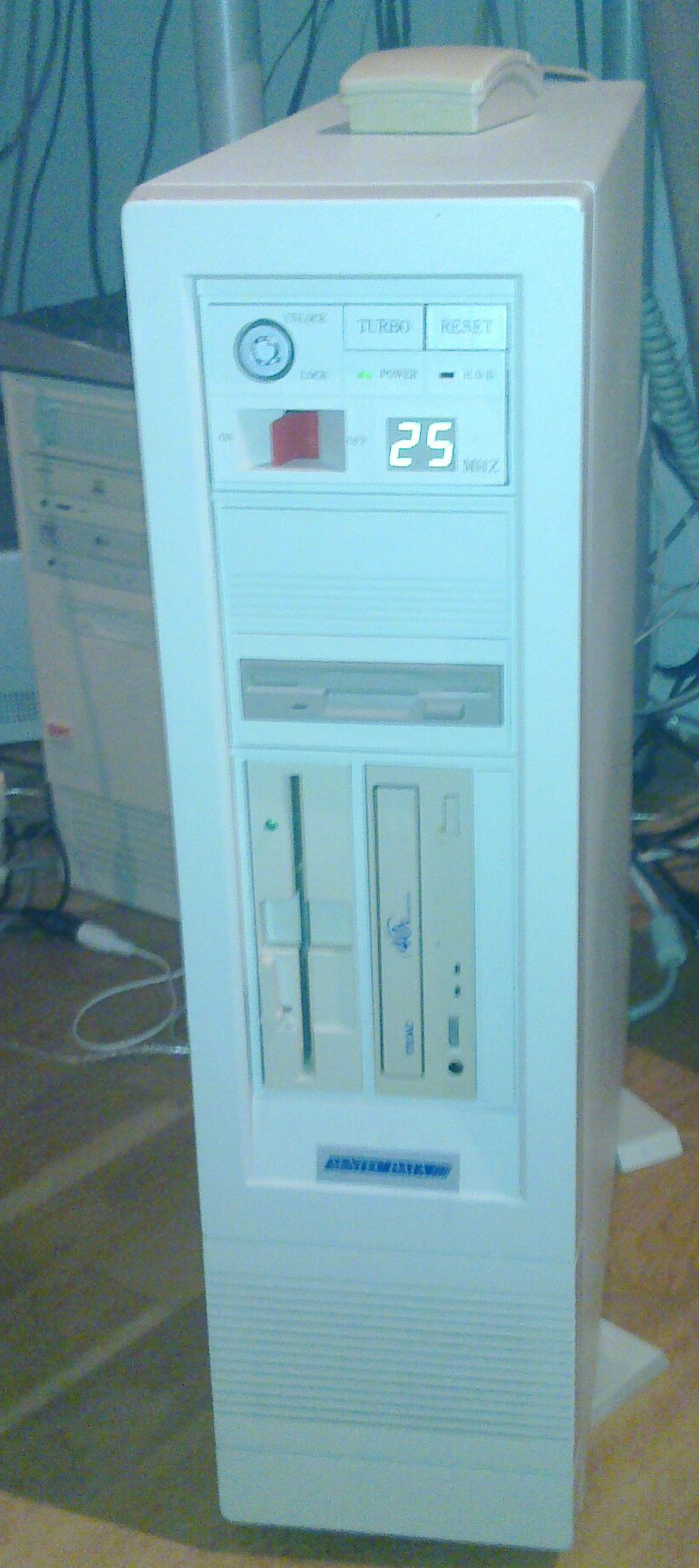
Figure 10 - System reassembled with a CD-RW drive
This machine was found by my friend h4xxel, and is also in his possession now. As things look now, OS/2 and/or Linux may additionally be installed on this machine. It is likely that we will use this as a platfrom for playing with home-built hardware, considering the available ISA slots and some lacking features. This post is pretty long as it is, so I will end it here. Follow ups may be posted in the future though!
Comments belong to their respective owners. By posting a comment, you agree and give the right for slaeshjag.org to publish or reject it. Your e-mail address will not be published or disclosed to a 3rd party, and is only used for return correspondance or verifying requests to delete comments.
You need JavaScript enabled to post a comment