Gamecube Controller Interface (part 1)
In this two-part article, I'm writing about my stumbling steps trying to interface a gamecube controller. The goal is to, using an LPC1114 microcontroller, interface 4 gamecube controllers with a computer. In this part, I get communication up with one controller on my improvised prototype build.
1 Generating the Basic Wave-forms
Let me be clear with one thing: this post contains no original research. I lazily followed the electrical protocol description at this website.
If you followed the link, you'll now know that the GameCube controller uses a single open-collector data line. Data is encoded by the length of a low pulse, 4 µs per bit. A 3 µs low pulse is a zero, a 1 µs low pulse is a one. There are no gaps between bits, unless you count the high idle state after the pulse.
There are a few ways to generate wave-forms like this. Either you could bit-bang it directly in code. I'm lazy and can't be bothered to write assembly, so I passed on that. Another way is to use the PWM controller for transmitting, and a timer input for receiving. I haven't used these peripherals before, and I couldn't be bothered to read the manual, so I passed on that. What I settled on is the universal solution for shoddy hacks requiring predictable timing: the SPI controller.
So the first step was to generate the interrogation command waveform. I'm not too concerned about the open collector part right now, so I'm measuring my output right from the MOSI pin of my micro-controller. Since the internal oscillator runs at 48 MHz, and the bit-clock is 250 kHz, I decided to run the SPI clock at 3 MHz. That gives me enough resolution to reasonably over-sample the signal, yet not an unreasonable amount of bits to process. A sample-rate of 1.5 MHz would probably work too. In order to achieve this with no gaps between bits, and to make sending bits easier, I configured the SPI controller to use frame format 1 (no gaps between bits) and a word-length of 12 bits.
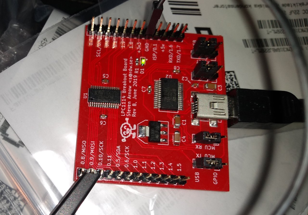
Figure 1 - Just measuring the signal right out from the micro-controller
As a test, I generated a square-wave at 1.5 MHz and checked in an oscilloscope that there are no gaps between words.
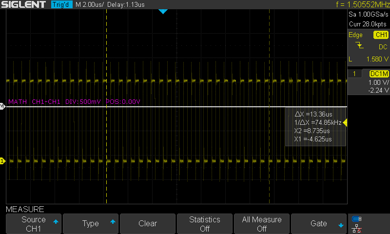
Figure 2 - Looking good, no gaps!
2 Making it Open Collector
Next step is to make the signal open collector. I decided to use an external transistor to make the code simpler (not having to fiddle around in registers to make MOSI high-impedance when listening for a response etc,) and a pull-up since the website linked earlier recommended one. My first attempt used a BC547, since that's all I had in through-hole at home. I had a gut-feeling it wouldn't be fast enough, but decided to give it a go anyway. I'm sure I could've squeezed more performance out of it if I tried, but it's been years since I didn't learn how to design with bipolar transistors.
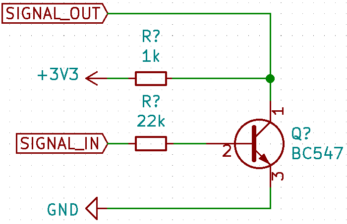
Figure 3 - Schematics for the attempt with a bipolar transistor
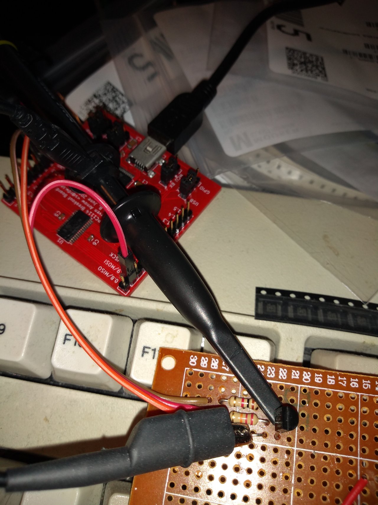
Figure 4 - Protoboard with the open-collector driver
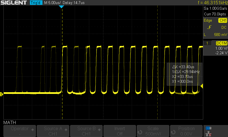
Figure 5 - Waveform produced with the bipolar open-collector driver
I don't know about you, but I can't tell a zero from a one, that BC547 really is chewing up the signal. So I bit the bullet and ordered some mosfets, stalling my progress for a few days.
After getting the mosfets, I quickly soldered up another board and tried it out. Nothing. No matter how long I looked at it, I couldn't figure out why a simple transistor inverter didn't work. I moved it to a breadboard and got it working, and the signal looked great.
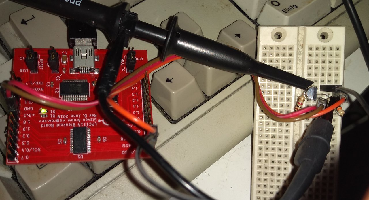
Figure 6 - Breadboard setup
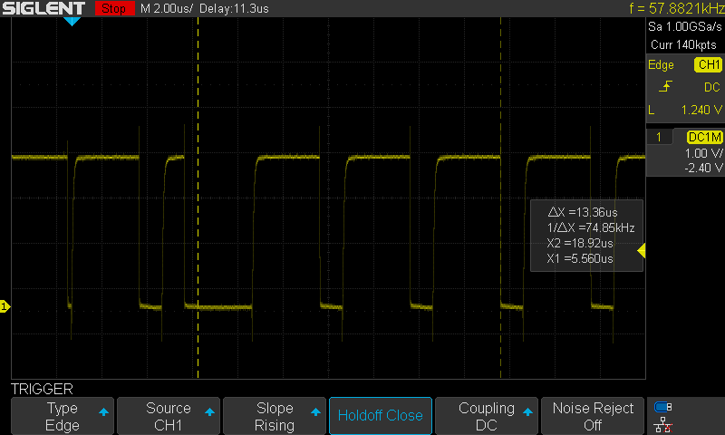
Figure 7 - Signal output with mosfet-based driver
Try bipolar
Fail with mosfet
Mosfet works on breadboard
Later failed on breadboard
Works on protoboard
Fully working on protoboard, able to decode its own output
Comments belong to their respective owners. By posting a comment, you agree and give the right for slaeshjag.org to publish or reject it. Your e-mail address will not be published or disclosed to a 3rd party, and is only used for return correspondance or verifying requests to delete comments.
You need JavaScript enabled to post a comment